Saturday, July 24, 2010

Experiment No.4 - voltage drop

In this exercise we where given 1 resistor, 1 5v1 400mw zener diode and one 1N4007 diode. With these I made a circuit and measured voltage drop at given points.

Vs = 10 & 15v
R = 1k ohms


10 Volts 15 Volts
Volt drop v1 5.04v 5.16v
Volt drop v2 .74v .76v
volt drop v3 5.78v 5.93v
Volt drop v4 4.19v 9.02v
Caculated current A 4.19mA 9.02mA
With the Zener diode in reverse polarity it drops it rated voltage which is why V1 is around 5v. Because the other diode is in foward polarity it only uses up its rated .7v.

Experiment No.3 - resistors and diodes

In this experiment we where given 2 resistors and a 5v1 400mW Zener diode and built a circuit.


R= 100 ohms
RL = 100 ohms
Vs = 12v , 10v , 15v

value of Vz = 4.94v
value of Vz = 4.69v
Value of Vz = 5.07v

As the supply voltage drops ans increases the zener diode should hold 5.1v but as it is a cheap zener diode this does not happen.

This type of circuit would be used for voltage regulation

Then I reversed the polarity of the zener diode,

Now the value of Vz is .84v, thsi is because this is the foward rated voltage drop of the zener diode.

Experiment No.2 - Diodes


In this experiment we where given two types of diodes, one a rectifer diode and the other a LED, we had to identify the anode and cathode of these two diodes using a multimeter.


The cathode end of the recifier diode is shown by a silver strip going around the end of it.


The cathode end of the LED is shown by the shorter leg which is the cathode or a flat spot on the LED next to the cathode end.


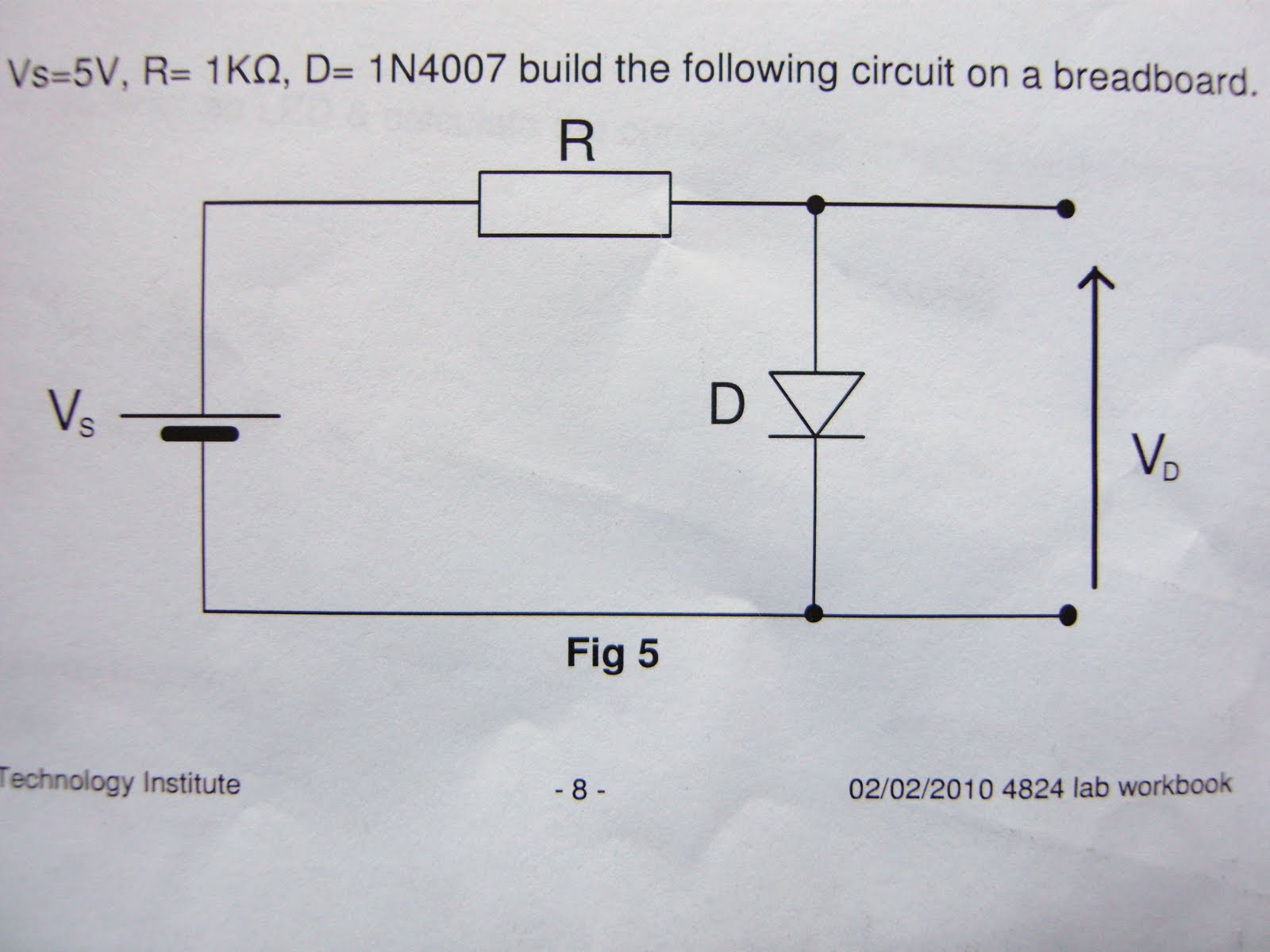
Next I had to caculate the value of current flowing through the diode in a circuit. I made this circuit using a 5v input, a 1kohm resistor and a 1N4007 diode on a breadboard.


Caculated current flow
5v - .7 = 4.3mA
I = 4.3/1 = 4.3mA
Measured
4.7mA
This reading is a little higher than i thought it would have been, but there is not much difference between the two.
The maximum value of the current that can flow through the diode is 1A.
For the 1kohm resistor the maximum value of V's so the diode operates in asafe region is 1000vs.
Next I replaced the diode with the LED and caculated the current.
Caculated current flow
5v - 1.94 = 3.06
I = 3.06/1 = 3.06ma
Measured
3mA
I observed that the LED uses more voltage (voltage drop) than the diode, this is because the LED needs voltage to light up.

Experiment No.1 - Resistors

The First experiment was to identify and test 6 different resistors. First I worked out their values by their colour bands, then measured the resistances of each one using a multimeter.

After I worked out the 6 resistances I chose two resistors and measured the resistances in series and parallel,.
Resistor 1 = 20.1 ohms
Resistor 2 = 330 ohms
Resistance in series
Rt = R1 + R2
20.1 + 330 = 350.1 ohms
Measured = 349 ohms
Resistance in parallel
1/Rt = 1/R1 + 1/R2
1/(1/20.1 + 1/350.1) = 19.009 ohms
Measured = 18.8 ohms
This shows that the resistance is greater when connected in series. This is becasue when connected in parallel the resistance is always going to be less than the lowest resistance.